
High-resolution reflection seismics
We record waves that return to the surface after reflecting off subsurface interfaces and transform them into a continuous section: the geometry of the bedrock, faults and deep aquifer bodies along the entire profile.
How it works
A source generates energy at the surface, and seismic waves propagate downwards. At each interface where acoustic impedance changes—the product of density and velocity—some of the energy is reflected upwards and recorded by a long array of geophones positioned along the profile. By moving the source and spread, each subsurface point is illuminated by many source–receiver pairs.
Traces sharing the same midpoint (CMP, common midpoint) are grouped together: reflections form hyperbolas, whose curvature depends on the velocity of the medium. Velocity analysis and normal moveout correction (NMO) flatten the hyperbolas; summing the traces (stack) strengthens the signal and attenuates noise. The seismic section is built by arranging the stacked traces from all CMPs.
Acquisition and processing
- Survey geometry design: spread length, geophone spacing and coverage
- Acquisition using P or SH waves with impulsive sources
- Spectral analysis, filtering and static corrections
- Velocity analysis and NMO correction
- Multiple-coverage stack
- Migration and depth conversion
- Integrated interpretation with boreholes and other surveys
Applications
- Bedrock geometry and depth
- Faults and tectonic discontinuities
- Deep aquifers and their lateral continuity
- Geothermal structures
- Sedimentary basins and buried palaeochannels
- Design of tunnels, dams and major infrastructure
- Support for deep well siting
One part of an integrated survey
Reflection sections are most effective when interpreted alongside other methods: seismic refraction and MASW define velocities in the uppermost metres, TDEM surveys and electrical resistivity tomography distinguish saturated layers, and borehole seismic surveys calibrate the velocity model against boreholes.
How a reflection section is built
At the upper left, rays travel from the sources, reflect off the interfaces and return to the geophones around the same midpoint. At the right is the CMP gather: the hyperbolas are flattened by NMO correction and summed. At the bottom, the stack section builds trace by trace, showing the dipping reflector and fault offset.
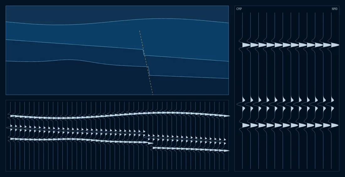
- Reflected rays and common midpoint
- Fault
- Seismic traces, variable area
Frequently asked questions
What is the difference between reflection and refraction seismics?
Refraction uses the first arrivals of waves travelling along interfaces where velocity increases with depth, and is suited to the uppermost metres and tens of metres. Reflection records waves that return to the surface after reflecting off each impedance contrast: it provides a continuous image of interfaces even when velocity does not increase with depth, and can investigate greater depths.
How deep can reflection seismics reach?
This depends on source energy, spread length, geophone spacing and ground absorption. The acquisition geometry is designed around the objective, from shallow bedrock to deep aquifers and structures of geothermal interest.
What do I receive at the end of the survey?
Stacked sections and, where useful, migrated and depth-converted sections; interpretation of the main reflectors and faults; the velocity model; and a technical report integrating the data with the geology, boreholes and other available surveys.
Often combined with this survey
Ready to start a project?
Send us the location and objective of the survey: we will propose the most suitable combination of methods and provide a detailed quote.